• About
  • Contact Us
  • Privacy Policy
  • Terms & Conditions
  • Disclaimer
Civilhex
  • Home
  • Civil Engineering
    • All
    • Foundation Engineering
    • Mathematics
    • Structural Engineering
    What is Civil Engineering

    Navigating the World of Civil Engineering: From Education to Mega Projects

    History of Concrete

    History of Concrete Timeline: Ancient World (6500 BC) to Modern Times

    solid-mechanics-case-study

    Solid Mechanics-Case Study Paper

    Beam Design Calculator

    Beam Design Calculator ACI 318-19 – Tension Reinforcement (Unknown Cross-Section)

    Beam-Design-Tension-Reinforcement-Unknown-Cross-Section-ACI-318-19

    Beam Design – Tension Reinforcement (Unknown Cross-Section) ACI 318-19

    Falling Head and Constant Head Method Permeability Test

    Falling Head and Constant Head Method Permeability Test

    Permeability

    Permeability Definition – Why is it Important in Civil Engineering?

    Mechanics-of-Solids-Question-Paper

    Mechanics of Solids-I – Term Paper & Answer Sheet

    Foundation Design rule-of-thumb checklist

    Foundation Design Rule-of-Thumb Checklist

    • Mathematics
  • Structural Engineering
  • Foundation Engineering
  • Construction
No Result
View All Result
Civilhex
No Result
View All Result
Home Civil Engineering Foundation Engineering

Seismic Refraction Survey – Determine Classification and Thickness of Various Soil Layer

Arjun Barman,CE by Arjun Barman,CE
December 2, 2023
in Foundation Engineering
Reading Time: 7 mins read
0
Seismic Refraction Survey
0
SHARES
421
VIEWS
Share on FacebookShare on Twitter

Seismic Refraction Survey is a part of the geotechnical investigation. In this article, you will find seismic refraction method and its procedure for the classification of soil and determining the soil layer thickness.

Table of Contents

  • Seismic Refraction Survey
    • Seismic Reflection Survey Method
    • Seismic Refraction Survey Limitations:
    • Example:
      • Solution:
    • Velocity Calculation
    • Thickness of Layers
    • Reference:
    • FAQ
      • What is seismic refraction survey?

Seismic Refraction Survey

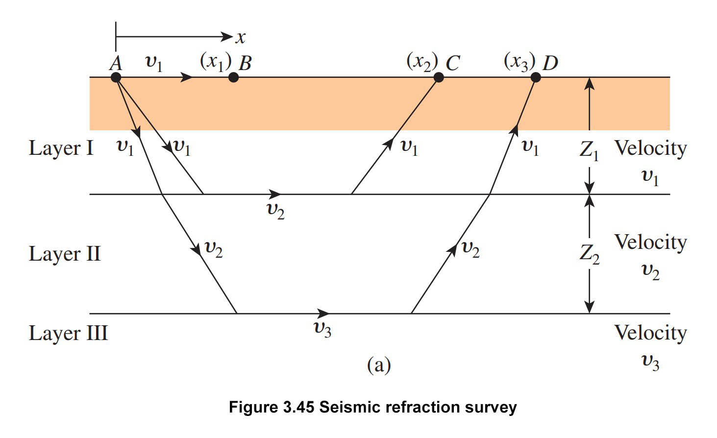
Seismic refraction survey is useful in obtaining preliminary information about the thickness of the various soil layers and the depth of rock or hard soil at a large site. Seismic refraction surveys are conducted by impacting the soil surface, such as at point A in Figure 3.45a, and observing the first arrival of the stress waves (disturbance) at several other points (e.g., B, C, D, ….). The impact can be created by a small explosion or hammer blow. Geophones can record the first arrival of disturbance waves at several points.

The impact on the ground surface creates two types of waves, one is P-waves (plane waves or compression waves) and another called S-waves (or shear waves). P-waves are faster than S-waves that’s why the first arrival of disturbance waves will be related to the velocities of the P-waves in various soil layers.

Seismic Refraction Survey
Figure 3.45a Seismic Refraction Survey

The velocity of the P-wave:

\upsilon \text{ }=\text{ }\sqrt{\frac{{{E}_{s}}}{\left( \frac{\gamma }{g} \right)}\frac{\left( 1-{{\mu }_{s}} \right)}{\left( 1-2{{\mu }_{s}} \right)\left( 1+{{\mu }_{s}} \right)}} \tag{3.79}

Where

Es = modulus of elasticity of the medium
γ = unit weight of the medium
g = acceleration due to gravity
μs = Poisson’s ratio

Seismic Reflection Survey Method

Step 1:  Obtain the times of the first arrival, t1, t2, t3, t4,. . . ., at various distances x1, x2, x3, x4,. . . , from the point of the impact.

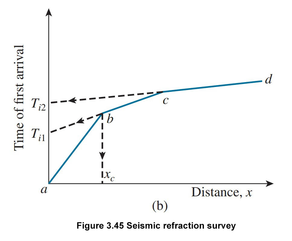
Step 2: Plot a graph of time t against distance x. The graph will look like the below Figure 3.45b.

Step 3: Calculate the slopes of the lines 0a, ab, bc, ….., :

Slope\text{ }of\text{ }0a=\frac{1}{{{\upsilon }_{1}}}
Slope\text{ }of\text{ }ab=\frac{1}{{{\upsilon }_{2}}}
Slope\text{ }of\text{ }bc=\frac{1}{{{\upsilon }_{3}}}

    Here, {{\upsilon }_{1}},\text{ }{{\upsilon }_{2}},\text{ }{{\upsilon }_{3}}, . . . . , are p-wave velocities in layers I, II, III, . . . . ., respectively (see figure 3.45a).

Seismic Refraction Survey
Figure 3.45b Seismic Refraction Survey

Step 4: Determine top layer thickness:

\tag{3.80}{{Z}_{1}}=\frac{1}{2}\sqrt{\frac{{{\upsilon }_{2}}-{{\upsilon }_{1}}}{{{\upsilon }_{2}}+{{\upsilon }_{1}}}}{{x}_{c}}

The value of {{x}_{c}} can be obtained from the plot which is shown in Figure 3.45b.

Step 5: Determine the second layer thickness:

\tag{3.81}{{Z}_{2}}=\frac{1}{2}\left[ {{T}_{i2}}-2{{Z}_{1}}\frac{\sqrt{\upsilon _{3}^{2}-\upsilon _{1}^{2}}}{{{\upsilon }_{3}}{{\upsilon }_{1}}} \right]\frac{{{\upsilon }_{3}}{{\upsilon }_{2}}}{\sqrt{\upsilon _{3}^{2}-\upsilon _{2}^{2}}}

Note: If you have trouble viewing the equation then view the page in desktop mode in your mobile browser.

Here, {{T}_{i2}} is the time intercept of the line cd in Figure 3.45b, extended backward.

(For detailed derivations of this equation and other related information, see the research paper “Dobrin, 1960, and Das, 1992”.)

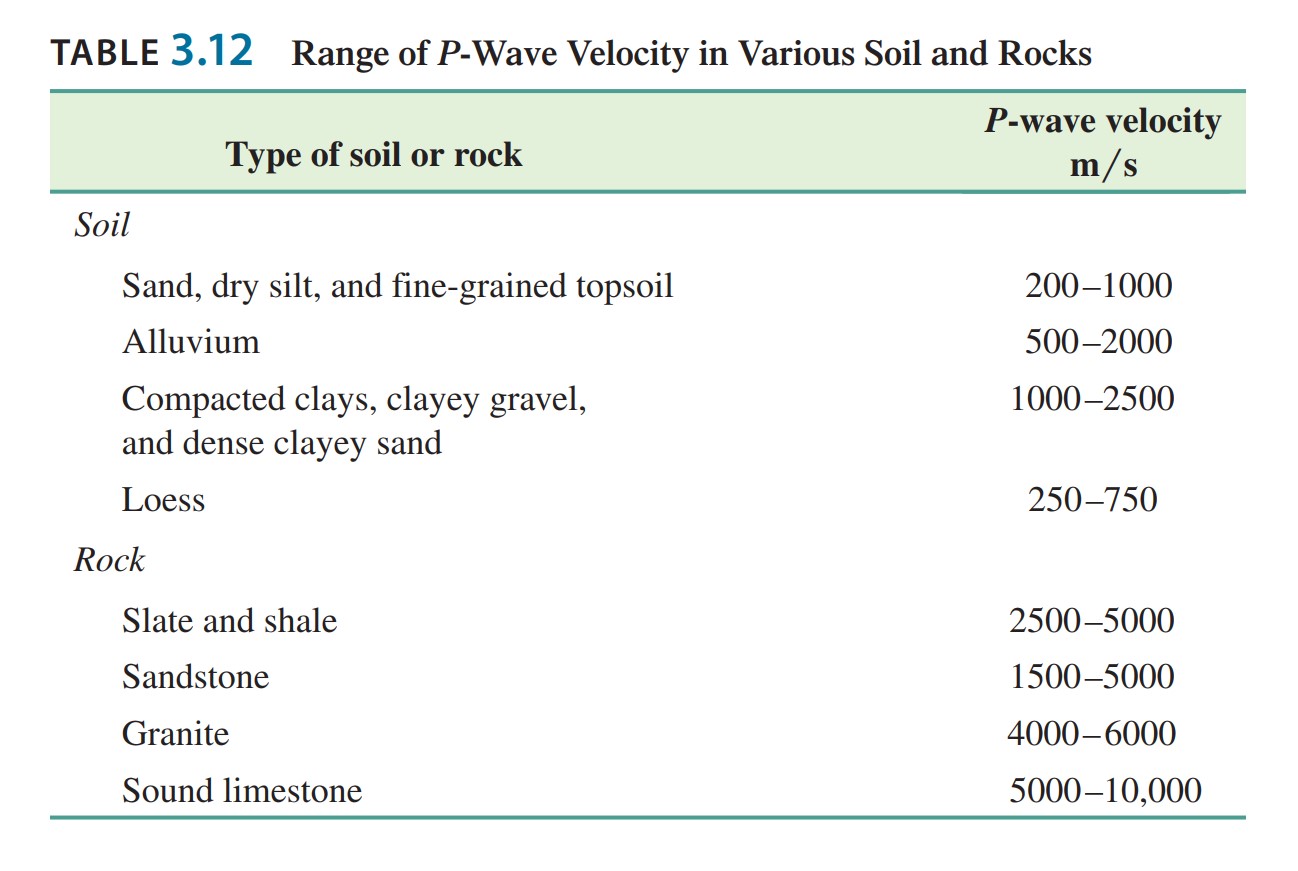
P-waves velocities indicate the types of soil or rock in various layers that are present below the ground surface. The range of the p-wave velocity that is encountered in different types of soil and rock at shallow depths is given below in Table 3.12.

Table 3.12: Range of P-Wave Velocity in Various Soil and Rocks

P-Wave Velocity in Various Soil and Rocks
Range of P-Wave Velocity in Various Soil and Rocks

In Seismic refraction survey there have two limitations and that must be kept in mind when analyze the results.

Seismic Refraction Survey Limitations:

  1. The general equation for the survey – that is eq. (3.80) and eq. (3.81) – are base on the assumption that the P-wave velocity {{\upsilon }_{1}}<{{\upsilon }_{2}}<{{\upsilon }_{3}}<.....
  2. When a soil is saturated below the water table, the p-wave velocity may be incorrect. Through water, P-wave can travel with a velocity of about 1500 m/s. For dry soil, loose soil, the velocity may be well below 1500 m/s. However, in a saturated soil condition, the waves will travel through water that is present in the void space with a velocity of about 1500m/s. If the presence of groundwater has not been detected, then the p-wave velocity may be erroneously interpreted that indicating a stronger material like sandstone is actually present in situ. In general, geophysical results should always be verified by the result obtained from the soil boring test.

Now, at the end of this session, an example problem is given below for perfect understanding.

Example:

The result of a seismic refraction survey at a site are given below:

Distance of geophone from the source of disturbance (m)Time of first arrival (t x 10­­­-3)
2.511.2
523.3
7.533.5
1042.4
1550.9
2057.2
2564.4
3068.6
3571.1
4072.1
5075.5
seismic refraction survey site data

Solution:

Velocity Calculation

Seismic refraction survey site data
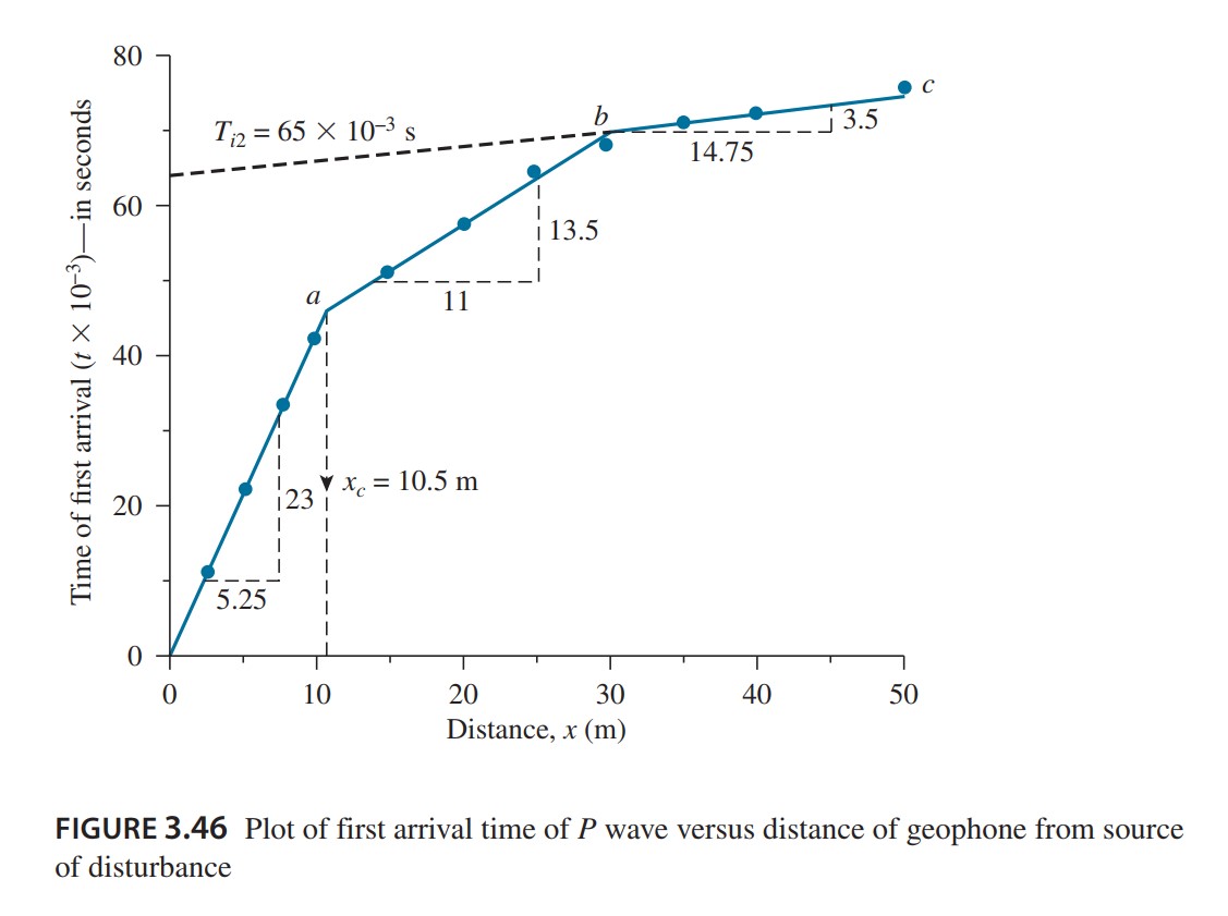
first arrival time of P wave versus distance of geophone from source
of disturbance

In Figure 3.46, the time of the first arrival of p-waves is plotted against the distance of the geophone from the source of disturbance (explosion or hammering). The plotted graph has three straight-line segments. The velocity of the top three layers can be calculated as:

Slope of segment:

0a=\frac{1}{{{\upsilon }_{1}}}=\frac{\text{time}}{\text{distance}}=\frac{23\times {{10}^{-3}}}{5.25}
{{\upsilon }_{1}}=\frac{5.25}{23\times {{10}^{-3}}}=228\text{ m/s (top layer)}

Slope of segment:

ab=\frac{1}{{{\upsilon }_{2}}}=\frac{13.5\times {{10}^{-3}}}{11}
{{\upsilon }_{2}}=\frac{11}{13.5\times {{10}^{-3}}}=814.8\text{ m/s (middle layer)}

Slope of segment:

bc=\frac{1}{{{\upsilon }_{3}}}=\frac{3.5\times {{10}^{-3}}}{14.75}
{{\upsilon }_{3}}=\frac{14.75}{3.5\times {{10}^{-3}}}=4214\text{ m/s (third layer)}

After analysis of the results given in Table 3.12, it indicates that the third layer is a Rock Layer.

Thickness of Layers

From Figure 3.46, {{x}_{c}}=10.5m , So

{{Z}_{1}}=\frac{1}{2}\sqrt{\frac{{{\upsilon }_{2}}-{{\upsilon }_{1}}}{{{\upsilon }_{2}}+{{\upsilon }_{1}}}}{{x}_{c}}

Thus,

{{Z}_{1}}=\frac{1}{2}\sqrt{\frac{814.8-228}{814.8+228}}\times 10.5=3.94m

Again, from (Eq. 3.81),

{{Z}_{2}}=\frac{1}{2}\left[ {{T}_{i2}}-2{{Z}_{1}}\frac{\sqrt{\upsilon _{3}^{2}-\upsilon _{1}^{2}}}{{{\upsilon }_{3}}{{\upsilon }_{1}}} \right]\frac{{{\upsilon }_{3}}{{\upsilon }_{2}}}{\sqrt{\upsilon _{3}^{2}-\upsilon _{2}^{2}}}

The value of {{T}_{i2}} (from figure 3.46) is 65 x 10-3 s. Hence,

{{Z}_{2}}=\frac{1}{2}\left[ 65\times {{10}^{-3}}-2\times 3.94\frac{\sqrt{{{4214}^{2}}-{{228}^{2}}}}{4214\times 228} \right]\frac{4214\times 814.8}{\sqrt{{{4214}^{2}}-{{814.8}^{2}}}}=12.66m

Thus, the rock layer lies from the surface of the ground at a depth of:

{{Z}_{1}}+{{Z}_{2}}=3.94+12.66=16.60m

Note: Equations and the number of equations which used in this article are taken from reference section source.

See this video to learn more about “what is seismic reflection?”

What is seismic reflection?

Watch this video for how to do seismic reflection surveys practically on the site.

seismic reflection surveys practically on the site

Reference:

Principles of Foundation Engineering (Ninth edition, 2019), “Braja M. Das, University Sacramento”, “Nagaratnam Sivakugan, College of Science & Engineering James Cook University”

FAQ

What is seismic refraction survey?

Seismic refraction survey is a method of determining the classification of soil (e.g. clay, silt, sandstone, granite, etc.) and the thickness of various soil layers by using an artificial seismic such as a small explosion or hammering.

ShareTweet
Arjun Barman,CE

Arjun Barman,CE

Meet Arjun Barman, a civil engineering enthusiast on a mission to become a structural engineering maestro. With an unwavering passion for the art of building, Arjun shares his expertise and love for civil engineering through his engaging writing. Join him on his exciting journey through the world of structures, as he simplifies the complexities and makes the wonders of civil engineering come to life, one article at a time. Direct contact: [email protected]

Related Posts

Permeability
Foundation Engineering

Permeability Definition – Why is it Important in Civil Engineering?

July 12, 2023
Foundation Design rule-of-thumb checklist
Foundation Engineering

Foundation Design Rule-of-Thumb Checklist

July 12, 2023
Electrical Resistivity Tomography Survey
Foundation Engineering

What Is Electrical Resistivity Tomography Survey – Procedure

September 16, 2023

Discussion about this post

  • Trending
  • Comments
  • Latest
What is Rebar-Rebar Sizes, Grade, and Types

Learn All About Rebar-Rebar Sizes, Grades, and Types

July 16, 2023
Soil Boring

Soil Boring – 4 Different Methods of Soil Boring

July 12, 2023
Seismic Refraction Survey

Seismic Refraction Survey – Determine Classification and Thickness of Various Soil Layer

December 2, 2023
Depth of Boring

Depth of Boring and Borehole Spacing for Soil Investigation

July 13, 2023
Transport-Traffic-Design

Traffic Design-An Accident Investigation Problem

0
what is concrete made of?

Concrete and Reinforced Concrete

0
What is Rebar-Rebar Sizes, Grade, and Types

Learn All About Rebar-Rebar Sizes, Grades, and Types

0
sprinkle-irrigation-systems

Sprinkler Irrigation Systems -Types of sprinkler

0

Test

December 2, 2023
What is Civil Engineering

Navigating the World of Civil Engineering: From Education to Mega Projects

October 26, 2023
Sustainable Building

Building for the Future: The Importance of Sustainable Building Design

July 13, 2023
History of Concrete

History of Concrete Timeline: Ancient World (6500 BC) to Modern Times

July 13, 2023

Popular Article

  • What is Rebar-Rebar Sizes, Grade, and Types

    Learn All About Rebar-Rebar Sizes, Grades, and Types

    421 shares
    Share 0 Tweet 0
  • Soil Boring – 4 Different Methods of Soil Boring

    0 shares
    Share 0 Tweet 0
  • Seismic Refraction Survey – Determine Classification and Thickness of Various Soil Layer

    0 shares
    Share 0 Tweet 0
  • Depth of Boring and Borehole Spacing for Soil Investigation

    0 shares
    Share 0 Tweet 0

Recent News

What is Civil Engineering

Navigating the World of Civil Engineering: From Education to Mega Projects

October 26, 2023
Sustainable Building

Building for the Future: The Importance of Sustainable Building Design

July 13, 2023
History of Concrete

History of Concrete Timeline: Ancient World (6500 BC) to Modern Times

July 13, 2023
SRM Concrete

Why SRM Concrete is the Top Choice for Commercial and Residential Projects

July 13, 2023

CIVILHEX

Inspiring Civil Engineers & Architects with a Treasure Trove of Information and Ideas!

Welcome to Civilhex, your ultimate online destination for civil engineers, structural engineers, architects, construction professionals, and civil engineering students. Explore various engineering topics, ranging from geotechnical, structural, foundation water resources, and transportation engineering. Stay up-to-date with the latest advancements in technology, cutting-edge research, comprehensive guides, and safety-related information. Civilhex is your go-to resource for all things civil engineering. Visit us today and enhance your knowledge in the field.

Follow Us

Browse by Category

  • Civil Engineering
  • Construction
  • Foundation Engineering
  • Mathematics
  • Structural Engineering
  • Uncategorized

Contact Us

Email: [email protected]
Phone: +1 213 376 3997

Location

185 Greenwich St, New York, USA NY 10007

Recent News

Test

December 2, 2023
What is Civil Engineering

Navigating the World of Civil Engineering: From Education to Mega Projects

October 26, 2023
  • About
  • Contact Us
  • Privacy Policy
  • Terms & Conditions
  • Disclaimer

© 2023 Civilhex - Civil Engineering

No Result
View All Result
  • Home
  • Civil Engineering
    • Mathematics
  • Foundation Engineering
  • Structural Engineering
  • Construction
  • About
  • Contact Us

© 2023 Civilhex - Civil Engineering

Welcome Back!

Login to your account below

Forgotten Password?

Retrieve your password

Please enter your username or email address to reset your password.

Log In

Add New Playlist

We use cookies on our website to give you the most relevant experience by remembering your preferences and repeat visits. Visit our Privacy and Cookie Policy.