Purlin Design
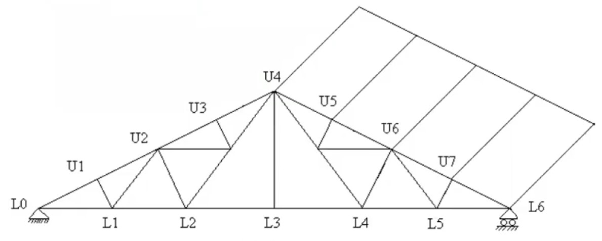
Purlin Design: In this article, we explain how to design purlin of a fink truss for a workshop structure. It is a simple basic design procedure for hand calculation checks. In actual practice it is not that simple, you must consider the section orientation of the purlin, earthquake load, snow load, service load check, and much more but don’t worry you can easily handle all these things by using structural analysis software. join our community for more civil structural engineering updates. Let’s move forward to the purlin design procedure.
Design a purlin with the following specifications:
a) Area of workshop = 12000 sft
b) Span of the roof truss = 127 ft
c) Height of the truss = 1/4 of the span
d) Spacing of the truss = 1/5th to 1/4th of the span
e) Wind velocity, v = 99.42 mph (Based on your local Building Code & Site location)
f) Roofing shall be corrugated galvanized iron sheet no. 20 B.W.G. whose wt. Is 2.25#/ft2
g) Allowable tensile strength, σ = 20 Ksi.
h) For all other specifications follow ASCE and AISE.
Calculation of Design Specification:
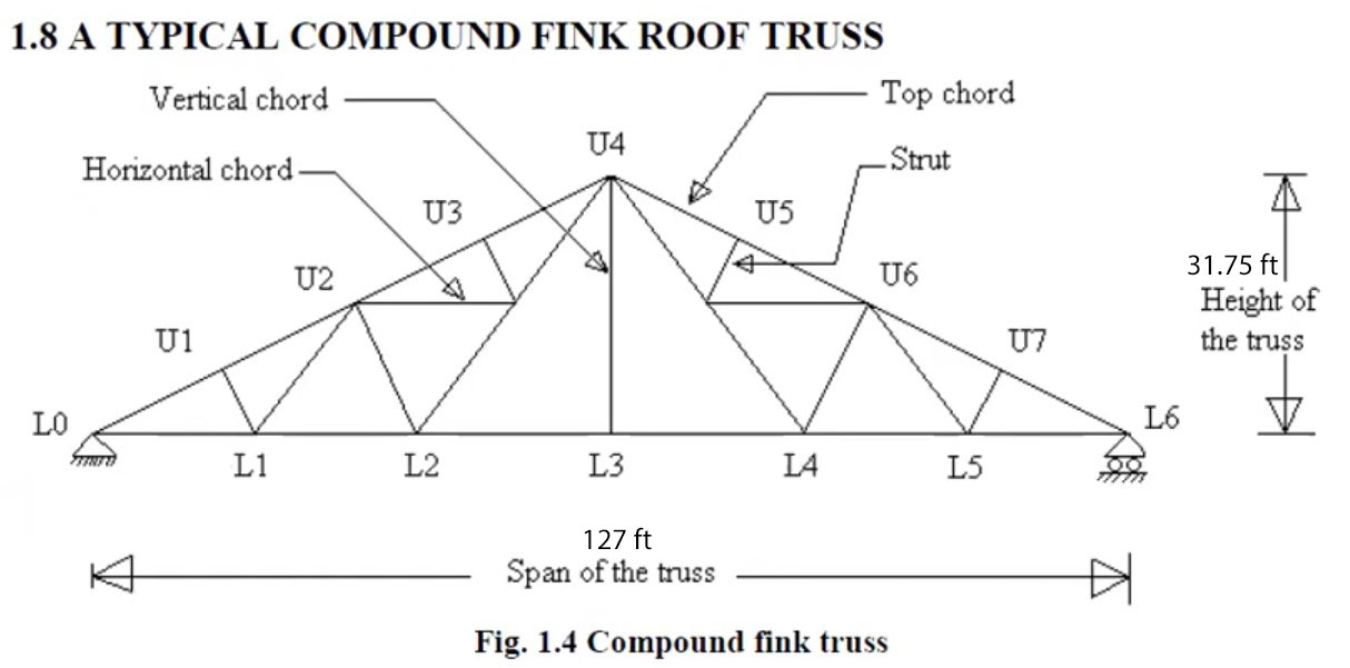
Step 1: Span of the truss, Sp = 127 ft
Step 2: Height of the truss, H= 1/4 × Span Sp= {(1/4) × 127} = 31.75 ft
Step 3: Approximate spacing of truss Sa = 1/5 × Span Sp = {(1/5) × 127} = 25.4 ft
Step 3: Length of the Workshop, L=\frac{\mathbf{Area}\text{ }\mathbf{of}\text{ }\mathbf{the}\text{ }\mathbf{workshop}}{\mathbf{Span}\text{ }{{\mathbf{S}}_{\mathbf{p}}}}
=\frac{12000}{127}=94.48\text{ ft}Step 5: No. of the truss, {{N}_{t}}=\frac{L}{{{S}_{a}}}+1 \\
\tag{} \begin{align}
 & \Rightarrow {{N}_{t}}=\frac{94.48}{25.4}+1 \\
 & \therefore {{N}_{t}}=4.71\approx 5 \\
\end{align}
Step 6: Actual Spacing of truss, ![]()
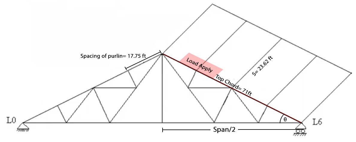
\Rightarrow S=\frac{94.48}{5-1}=23.62\text{ ft}Step 7: The Length of the upper left half (Top Chord)
\sqrt{{{H}^{2}}+{{\left( \frac{{{S}_{p}}}{2} \right)}^{2}}}=\sqrt{{{31.75}^{2}}+{{\left( \frac{127}{2} \right)}^{2}}}=71\text{ ft}Step 8: The angle of inclination upper chord
\theta ={{\tan }^{-1}}\left( \frac{H}{\frac{{{S}_{p}}}{2}} \right)\theta ={{\tan }^{-1}}\left( \frac{31.75}{\frac{127}{2}} \right)=26.56{}^\circ Step 9: Wind Load, P=kV2
Where,
k= 0.003
V=99.42 mph
P=kV2 = 0.003 × 99.422= 29.65 lb/ft
\therefore {{P}_{n}}=P\times \frac{2\sin \theta }{1+{{\sin }^{2}}\theta }\Rightarrow {{P}_{n}}=29.65\times \frac{2\sin 26.56}{1+{{\sin }^{2}}26.56}=22.1\text{ lb/ft}▶️Design of Purlin:
(i) Length of purlin = length of workshop = 94.48 ft
(ii) Spacing of purlin = Top chord / 4= 71/4= 17.75 ft
(iii) Number of purlins = 4+1=5
(iv) Purlin is subjected to 3 types of loads as follows:
a) Dead load of roof = spacing of purlin × 1 × wt. of CGI sheet
= 17.75 × 1 × 2.25 = 39.94 lb/ft
b) Dead Load due to wind = spacing of purlin × 1 × Pn
= 17.75 × 1 × 22.1 = 392.28 lb/ft
c) Self weight of purlin = 3lb/sq-ft. area of the roof (Assumed)
∴ Self-load of purlin = 3 × 17.75 × 1 = 53.25 lb/ft
Total weight of purlin: w = (a)+(b)+(c)
= (39.94+392.28+53.25) = 485.47 lb/ft
Calculate Maximum Moment:
Here,
Actual Spacing of truss S = length of purlin
\tag{}\begin{align}
  & {{M}_{max}}=\frac{w{{S}^{2}}}{8} \\
 & \Rightarrow {{M}_{max}}=\frac{485.47\times {{23.62}^{2}}}{8}=33855.73\text{ lb-ft} \\
\end{align}
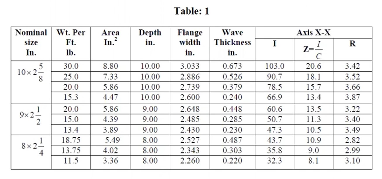
Section Modulus, ![]()


