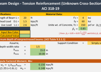
In this article, you going to learn about beam design, how to calculate the area of tension reinforcement in a beam and how to determine a beam-unknown cross-section by using ACI 318-19 design code. We also give a beam design example for better understanding and also gave beam design formulas with reference.
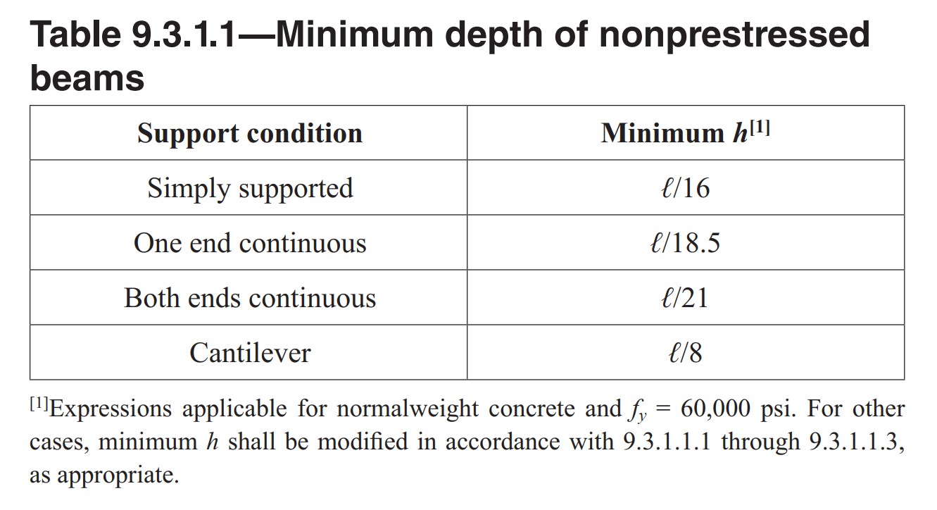
Step 1: Minimum depth of nonprestressed beams: (ACI Table 9.3.1.1)
Step 2: Ultimate Load: Wu
Step 3: Ultimate Moment: Mu
\tag{4.26d} {{\rho }_{\max }}=0.85{{\beta }_{1}}\frac{f_{c}^{'}}{{{f}_{y}}}\frac{{{\varepsilon }_{u}}}{{{\varepsilon }_{u}}+{{\varepsilon }_{t,\min }}}Step 5: Calculate bd2 from Nominal Moment: ![]()
Step 6: Find the trial size of the beam
Step 7: Calculate the area of steel
Step 8: Check for 𝜙 = 0.9
Step 9: Rebar calculation & Detailing
Beam Design Example for Unknown Cross-section as per
ACI 318-19:
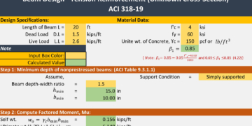
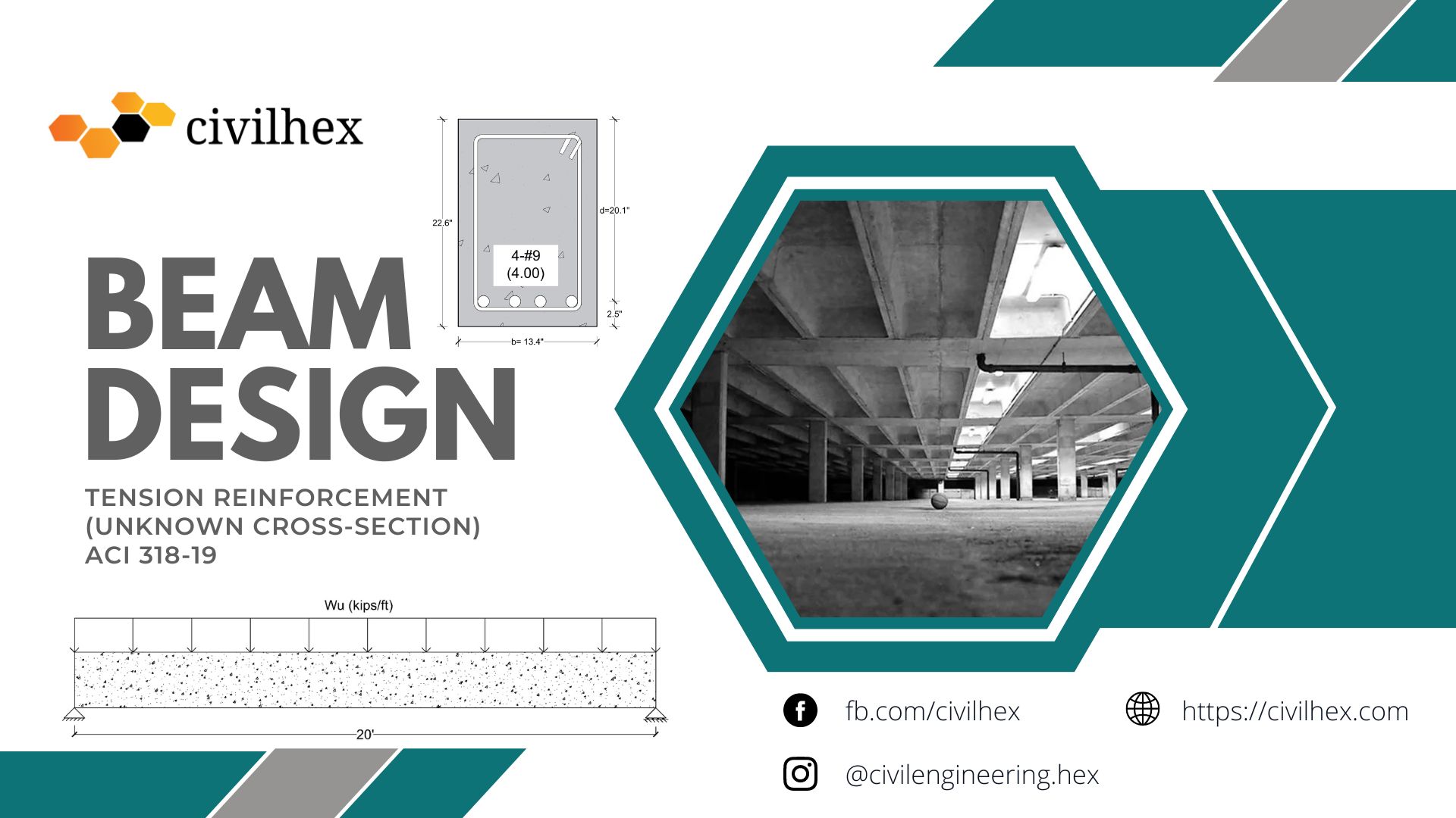
Find the concrete cross-section and the steel area required for a simply supported rectangular beam with a span of 20 ft that is to carry a calculated dead load of 1.5 kips∕ft and a service live load of 2.6 kips∕ft, as shown in Figure below. Material strengths are fc′ = 4000 psi and fy = 60,000 psi.

Solution
Given,
L = 20 ft
Dead Load = 1.5 kips/ft
Live Load = 2.6 kips/ft
Unit weight of concrete, γc = 150 pcf (lb/ft3)
f’c = 4000 psi
fy = 6000 psi
β1 = 0.85
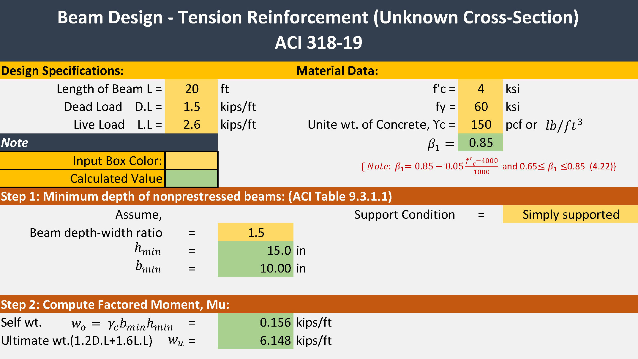
Step 1: Minimum depth of nonprestressed beams: (ACI Table 9.3.1.1)
Assume, Beam depth-width ratio = 1.5 (h/b=1.5)
hmin= L/16 = (20*12)/16= 15 inch
bmin= 15/1.5 = 10 inch
Step 2: Ultimate Load: Wu
Self-weight Wo = ![]()
Ultimate load
Wu = 1.2DL + 1.6LL = 1.2(wo+DL)+1.6LL
= 1.2(0.156+1.5)+1.6(2.6)
Wu = 6.147 kips/ft
Step 3: Ultimate Moment: Mu
For simply supported beam
Maximum moment Mu:
\begin{align}
  & {{M}_{u}}=\frac{{{W}_{u}}{{L}^{2}}}{8}=\frac{(6.147){{(20)}^{2}}}{8} \\
 & {{M}_{u}}=307.35kips-ft \\
\end{align} \tag{}
Step 4: Reinforcement ratio:
\begin{align}
  & {{\rho }_{\max }}=0.85{{\beta }_{1}}\frac{f_{c}^{'}}{{{f}_{y}}}\frac{{{\varepsilon }_{u}}}{{{\varepsilon }_{u}}+{{\varepsilon }_{t,\min }}} \\
 & \to {{\rho }_{\max }}=0.85*0.85*\frac{4}{60}*\frac{0.003}{0.003+0.005} \\
 & \to {{\rho }_{\max }}=0.0180 \\
\end{align} \tag{}
Note: Mobile users must use desktop mode to view equations correctly.
For Economy Use 60%-80% of the maximum reinforcement ratio. This is required for Underenforcement beam design.
{{\rho }_{design}}=0.8*{{\rho }_{\max }}=0.0145Step 5: Calculate bd2 from Nominal Moment:
\phi {{M}_{n}}=\phi \rho {{f}_{y}}b{{d}^{2}}\left( 1-0.59\frac{\rho {{f}_{y}}}{f_{c}^{'}} \right)\tag{}\begin{align}
& {{M}_{u}}=\phi {{M}_{n}} \\
& 307.35*12=0.9*0.0145*60*b{{d}^{2}}\left( 1-0.59\frac{0.0145*60}{4} \right) \\
& \therefore b{{d}^{2}}=5403.79i{{n}^{3}} \\
\end{align}Step 6: Find the trial size of the beam
Used,
d = 1.5b
d2 = 2.25b2 (Square both side)
bd2 = 2.25b3 (both sides multiply by b)
Now,
2.25b3 = 5403.79 in3
b = 13.4 inch
So, d= 1.5b= 1.5*13.4 = 20.1 inch
So, trial size of the beam
b = 13.4 inch
d = 20.1 inch
Note: You can assume b=14 in & d=20.5 in for more practical usages. For this example, we are using it as it is.
Step 7: Calculate the area of steel
{{A}_{s}}={{\rho }_{design}}bd=0.0145*13.4*20.1=3.90\text{ }i{{n}^{2}}Minimum flexural reinforcement (ACI 9.6.1.2):
{{A}_{s,\min }}\text{ larger of }\left\{ \begin{matrix}
   \frac{3\sqrt{f_{c}^{'}}}{{{f}_{y}}}{{b}_{w}}d=0.85\text{ i}{{\text{n}}^{\text{2}}}  \\\\
   \frac{200}{{{f}_{y}}}{{b}_{w}}d=0.90\text{ i}{{\text{n}}^{\text{2}}}  \\
\end{matrix} \right. \tag{4.37a}
\therefore {{A}_{s,\min }}=0.90\text{ i}{{\text{n}}^{2}}\text{ OK}\text{.}Note: ![]() must be in psi.
must be in psi.
Step 8: Check for 𝛟 = 0.9 (tension control)
a=\frac{{{A}_{s}}{{f}_{y}}}{0.85f_{c}^{'}b}=\frac{3.90*60}{0.85*4*13.4}=5.13\text{ in} \tag{4.28}c=\frac{a}{{{\beta }_{1}}}=\frac{5.13}{0.85}=6.03\text{ in}{{\varepsilon }_{t}}={{\varepsilon }_{u}}\frac{d-c}{c}=0.003*\frac{20.1-6.03}{6.03}=0.007>0.005\text{ OK}If you do not reduce the value of ![]() then It becomes exactly 0.005 or maybe less. This means the reduction factor 𝛟 = 0.9 it doesn’t applicable. So you must reduce the
then It becomes exactly 0.005 or maybe less. This means the reduction factor 𝛟 = 0.9 it doesn’t applicable. So you must reduce the ![]() value as
value as ![]() .
.
Step 9: Rebar calculation & Detailing
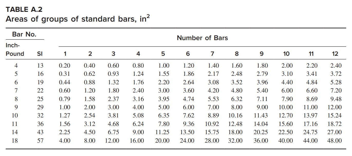
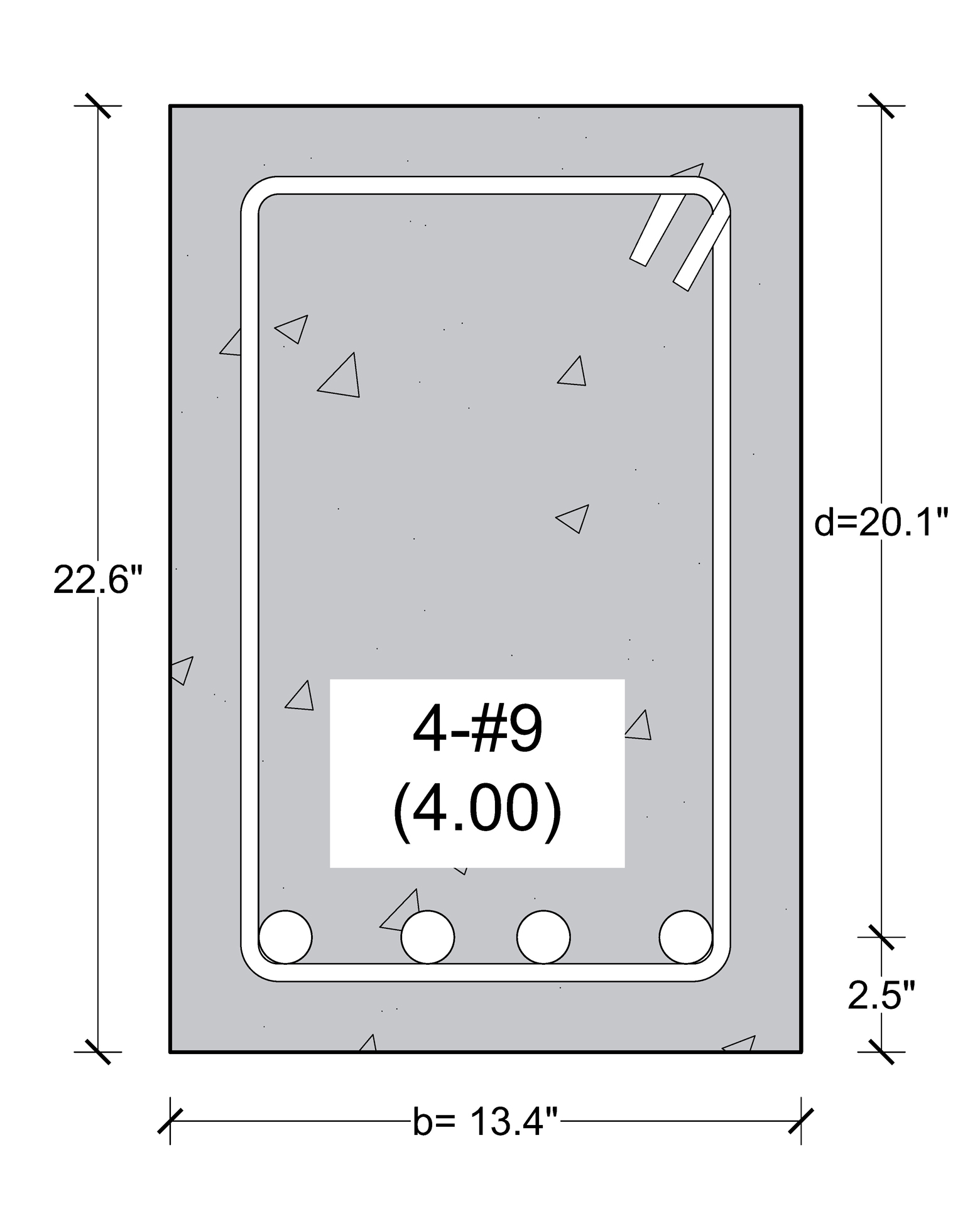
Used 4-#9 (4.00 in2) bar
{{A}_{s,provide}}(4.00\text{ }i{{n}^{2}})>{{A}_{s,required}}(3.90\text{ }i{{n}^{2}})\text{ OK}Assuming 2.5 in. concrete cover from the centroid of the bars,
h = d+2.5” = 20.1+2.5=22.6 inch
Beam Size:
b=13.4 inch
h=22.6 inch
Reference
- Design of Concrete Structures Sixteenth Edition by David Drawin & Charles W. Dolan.
- Building Code Requirements for Structural Concrete (ACI 318-19)
- ASCE 7_22 Minimum Design Loads and Associated Criteria for Buildings
Check this Beam Design Calculator ACI 318-19
See more Article:


